Help: Topics
Additional details & instruction about KineBody are provided on this page.
Rotation Axes
The straight red, green, and blue lines in the KineBody viewing area are rotation axes. Each one generally corresponds to one rotational degree of freedom, or equivalently, to one of the currently visible rotation sliders. When you adjust a rotation slider, you can observe a body part pivoting about one of these lines. For instance, when you rotate the full body, it should be relatively clear that the ‘tilt’ angle is associated with rotations about the green axis, and the ‘spin’ angle measures rotation about the blue axis. The association between axes and sliders is indicated by the colored rectangle, at the right or top end of the slider (spin ≡ blue, tilt ≡ green).
When you select & rotate a joint, you’ll see 1, 2, or 3 rotation axes displayed, depending on the joint. Along with the axes, an equal number of joint sliders will also be displayed (to the right of the distance slider, with the gray background). Like the (white) body sliders, the joint sliders will include a colored rectangle at one end, to indicate the associated axis. From the correspondence between slider names & their small rectangle colors, and axis colors, you can determine the name of the motion associated with each axis. For example, rotating the hip around the red axis constitutes flexion or extension.
[Note also when you select a joint, the colored rectangles for the spin and tilt body sliders are ‘turned off’. These sliders can still be used to rotate the body, but the spin & tilt axes are no longer visible; instead, the colored lines are being used to show the joint rotation axes].
As you experiment with various rotations, you may note that some of the axes change direction (when you rotate about a different axis), but other axes remain fixed, no matter what rotations you apply. For example, when you tilt the body, the blue axis changes direction, but adjusting spin or tilt doesn’t change the green axis direction. You can see a similar effect if you adjust the hip joint: of the three axes, the red one remains fixed to the hip bone, but the blue and green axes may change direction, depending on the adduction/abduction and internal/external rotation angles.
For KineBody joint rotations, there’s a consistent pattern in the way the different axes move or remain fixed. [For KineBody body rotations, see below]. For 3DOF joints (such as the main (gleno-humeral) shoulder joint, or the hip joint (ilio-femoral)), the pattern is as follows:
- The red and blue axes are ‘fixed’ to the bones on either side of the joint (red ≡ proximal, blue ≡ distal).
- The green axis is always perpendicular to both the red and blue axes.
- The red axis may be inclined relative to the blue axis: it doesn’t have to be perpendicular.
- The previous 2 statements imply that, if the red & blue axes aren't coincident or parallel, they form a plane, which is perpendicular to the green axis.
[Since the rotation axes don’t have to be mutually perpendicular, they can't be used as a Cartesian coordinate system; however, they can & do serve as a Cardan (or Euler) angle coordinate system. All of the joints in KineBody have an underlying Cardan angle system, which makes it possible to define their positions precisely as well as practically. It's not necessary to understand the math behind Euler angles to operate KineBody. On the other hand, if you have some background in Euler angles, the pattern described here should be relatively easy to understand.]
The pattern is further characterized by how the axes change direction:
- When you rotate the joint around the red axis, the green & blue axes change direction.
- When you rotate about the green axis, the blue axis changes direction.
This pattern can be understood as a ‘hierarchy’, in the order Red > Green > Blue (RGB). Under this hierarchy, if you pick one axis and rotate about it, the directions of the other axes will change in all ‘lower’ levels (i.e., to the right)
As a supplement to this pattern, KineBody uses the following convention: the blue axis is usually aligned with the long axis of the distal bone. Then, rotations that move the blue axis tend to ‘swing’ the distal bone, whereas rotations around the blue axis cause it to ‘spin’ (a.k.a. internal/external rotation, pronation/supination, or similar).
The RGB pattern generally holds for all 3DOF joints. For 2dof joints, a ‘sub-sequence’ of the RGB pattern is used, for example:
- the tempero-mandibular joint uses RG (red & green axes, and rotating red can cause green to change direction)
- the knee (tibio-fibular) joint uses RB (red & blue axes, with red causing blue to change direction)
For 1DOF joints, the axis may be any color: the humero-ulnar (elbow) joint is red, but the radio-ulnar (foream) joint is blue. Blue is generally used when the joint permits rotation about the long axis of the distal bone, as mentioned above.
One important consequence of the RGB pattern has to do with KineBody joystick operation:
- when red & green axes are displayed, you can move the joint in two directions at once, without need for special keystrokes.
- to rotate about a blue axis, you have to press the [Alt] key, while dragging. (Mnemonic: ‘Alt’ has 3 characters => 3rd axis)
- (The RGB pattern and joystick operation are connected in many other ways, but belaboring these isn't useful: the whole point of this design is to make the technique more intuitive – understanding these relations isn't required!)
The RGB pattern just described holds for most joints, but you should understand that there are several exceptions:
- The radio-ulnar joints show a blue axis, but [Alt] isn't necessary, because with 1DOF there’s no confusion.
- The acromio-clavicular joint violates most of the rules above. It employs some special techniques to ensure the scapula follows the posterior ribcage, and these interfere with the regular roles for the rotation axes.
- The neck and lumbar spine, follow the RGB pattern, but only ‘loosely’. The axes in this case aren't true rotation axes, and the hierarchy breaks down, as rotations about any one axis can affect the others – there’s no priority in the ordering.
For KineBody body rotations, the RGB pattern holds as well, but there are some other exceptions. When moving the body, the red axis is attached to the screen, and is directed perpendicular to it. (The red axis is usually hard to see, because it’s pointing directly at you. However, you can see it if you displace the body axes horizontally or vertically away from the center of the viewing area, thanks to the perspective projection).
In KineBody Pro, you can rotate the body around the red axis. The red axis is related to the blue and green axes using the same RGB hierarchy as defined above. However, the KineBody joystick operation is slightly different: regular operation (without modifier keys), causes rotation about the blue & green axes, and the [Alt] key allows you to rotate around the red axis. (Once again, the mnemonic ‘Alt’ = 3 characters = 3rd axis, is useful).
In KineBody Basic, you can't rotate the body around the red axis. Nevertheless, there’s still a hierarchy: in this case it's simply a ‘GB’ system (i.e., rotating about green can cause the blue axis to change direction). The joystick allows you to rotate about the blue and green axes together; there’s no need for the [Alt] key.
In summary: the rotation axis colors in KineBody aren't arbitrary: rather, they exhibit a consistent pattern of properties and behaviors. Operation of the KineBody joystick is strongly connected to this pattern, so that you can easily move (almost) any joint in the same manner as any other joint.
Degrees of Freedom
In a loose sense, a ‘degree of freedom’ (DOF) refers to one of the ‘directions’ you can move a joint. For example, the glenohumeral joint of your shoulder has three primary degrees of freedom:
- movement within a sagittal plane (flexion & extension)
- movement away from or toward that plane (abduction & adduction)
- rotation about an axis along the bone (internal & external rotation)
In contrast, the humero-ulnar joint of your elbow has one primary degree of freedom (flexion & extension). It’s important to understand, however, that ‘degrees of freedom’ are not the same as ‘directions’. Differences include:
- ‘Directions’ is a very vague term. For example, you can move your arm to the left, or you can lift your knee upward, but the effect of these motions on your joints depends on how your body is oriented. For human joint motions, it’s helpful to describe the motions in relative terms, i.e., how one body part moves relative to another. Thus, you can move your arm away from your body (abduction), or you can move your knee in a sagittal plane (flexion/extension) so as to change the angle between femur and tibia, etc. For a joint, degrees of freedom generally refers to relative motion, between the adjacent bones.
-
A ‘direction’ can refer to:
- either of two possible motions along a line (for instance, up or down), or
- both of these together (vertical).
It’s also important to understand that degrees of freedom do not refer to the measurement of an angle in degrees! [For instance, don't ever refer to a 30° range of motion as ’30 degrees of freedom’! Although the words are logically correct, they're not 'idiomatically' correct. ]
More specifically, ‘degrees of freedom’ refer to the independent coordinates required to completely specify a position or direction. For example, if you’re using a touch screen, the position of your fingertip as it slides along the screen has two degrees of freedom, which can be specified using Cartesian (x, y) coordinates relative to the screen edges. Note how this differs from ‘directions’: you can move your finger an infinite number of directions, or, to an infinite number of positions.
Generally, a point in physical space is considered to have 3 degrees of freedom, corresponding to the Cartesian (x,y,z) coordinates required to specify its position. It’s not essential to use Cartesian coordinates: you could alternatively express the position using cylindrical (r, θ, z) or spherical (ρ, θ, φ) coordinates. Regardless of the type of coordinates, the number of degrees of freedom remains the same. For a rigid body in space, there are 6 degrees of freedom: 3 to specify the position of one point on the body, and 3 to specify the orientation of the body relative to that point. The orientation is often expressed as 3 rotations: for instance, the orientation of a flying aircraft is often specified in terms of the the yaw, pitch, and roll angles, relative to the earth.
The number of degrees of freedom is reduced whenever motion constraints are present. If you consider your fingertip to be a ‘point’, it has 3 degrees of freedom in general, but only 2DOF while it remains in contact with a touch screen. The touch screen contact is a 1 DOF constraint, i.e., you’re prevented from moving your finger into the screen.
It’s useful to consider a similar case, of moving your fingertip over the surface of a curved object, for example, a ball. In this case, there is once again a 1 DOF constraint, preventing you from moving your fingertip into the ball; thus, the position of your fingertip on the ball surface has two degrees of freedom – this is so even though the ball surface is three dimensional. This makes sense if you consider the analogous case of specifying your global position on the earth’s surface: only latitude and longitude are needed (unless you’re flying, scuba diving, etc).
KineBody represents the position of the full skeleton using 5 or 6 degrees of freedom, depending on which version of KineBody you’re using:
- KineBody Basic (our free edition) offers 5 DOF: 3 translations (horizontal, vertical, distance) and 2 rotations (spin, tilt). Spin is the rotation about the body’s longitudinal axis, whereas tilt is the inclination of that axis relative to the viewing screen.
- KineBody Pro (our subscription edition) offers you a choice of 5 or 6 DOF: the 6th DOF adds a 3rd rotation called 'dial angle', which allow rotations about an axis perpendicular to the screen.
The 5 DOF case is simple to use and understand, and is adequate for most purposes, whereas the 6th degree of freedom introduces more complexity. Note that the reference for full body motion is the thorax, i.e., the rotation values are defined relative the ‘home’ position of the thorax, without regard to the positions of any other joints. Likewise, full body translations are defined to be those of the thorax (measured relative to an origin at your eye).
Joints in KineBody are represented using 1 to 3 DOF – the number and direction depends on the joint. As with the full skeleton, there is one slider control for each degree of freedom. All of the joint DOF’s are rotational – KineBody doesn’t currently implement translational DOFs for joints (despite their importance, for instance, at the tempero-mandibular joint). Hence, a 3 DOF joint (such as the gleno-humeral joint at the shoulder) permits 3 types of rotation. Note that the number of DOFs at a joint is defined by the relative motion between the adjacent bones – this doesn’t change whether you consider both bones to be free in space or for one of them to be fixed.
It may be useful to understand the number of DOFs at a joint in terms of the constraints: For instance, a 3 DOF ball & socket joint can be understood as follows:
| total DOF for two independent bones in space | 12 | (2 bones x 6 DOF per bone) |
| debit for considering only relative motion | -6 | constraint DOFs |
| debit for ball & socket joint | -3 | constraint DOFs (ie, 3 translations are prevented) |
| Net | 3 | actual DOFs |
KineBody currently implements more than 75 DOF in total among all joints (of which over 60 are 'unique', when you discount left/right symmetry). Unfortunately, it doesn’t currently allow all possible human joint motions. Joints within the hands and feet are a priority, but aren't yet available simply due to the significant effort required, to implement more than 40 additional (unique) DOFs. Apart from these, the DOF available in KineBody have been selected & prioritized using multiple criteria, to focus on the following
- Large full body motions (e.g., those used for locomotion, bending, reaching/throwing, looking around, etc). Thus, for example, joints within the thorax (i.e., between thoracic vertebrae & the costo-vertebral joints) are a low priority owing to their small motion ranges.
- Readily available biomechanics data (i.e., locations of joint centers and axes, plus ranges of motion). Since the available scientific research is often medically focused, these tend to be the joints that are frequently injured or ones that commonly exhibit degeneration.
- Rotational DOF (as opposed to translational). Most translational DOF are associated with small, accessory movements (a.k.a. ‘play’ or ‘backlash’). One exception is the ‘jutting’ translational motion of the jaw (tempero-mandibular joint protrusion/retrusion); this DOF will require additional software modifications to allow translation.
For some joints, different DOF can be defined, corresponding to different coordinate conventions. For example, the acromio-clavicular joint can be configured to define DOFs relative to the cardinal planes [1], but research literature sometimes uses motions relative to alternative axes, along the plane and spine of the scapula [2]. KineBody follows the latter convention, allowing the measured & published ranges of motion to be used directly, i.e., without requiring additional coordinate transformations.
An important notion related to degrees of freedom is the concept of euler ‘sequences’, i.e., the order in which the rotational degrees of freedom are applied, when a body is rotated to a position ‘between’ (or, in a combination of) the independent degrees of freedom. For more info, stay tuned for a future writeup on Euler angles.
References
- Neumann, Kinesiology of the Musculoskeletal System, 2nd Ed (ch 5).
- Ludewig, et al., 'Three-dimensional Scapular Orientation and Muscle Activity at Selected Positions of Humeral Elevation', Journal of Orthopaedic & Sports Physical Therapy, 24:2, Aug 1996.
FFI
- Degrees of Freedom
- Coordinate systems: Cartesian, Cylindrical, & Spherical.
Distance vs. Zoom
In KineBody, a Distance slider is provided to make the objects appear larger or smaller, instead of a conventional Zoom slider. This approach makes it possible to use physically meaningful position measurements. For example, if the distance slider’s numeric readout says 5.0 (meters), KineBody appears the same size as a physical human (full grown, ≈1.8m tall) at that same distance. This isn't possible using a Zoom scale – zoom is normally defined as a simple, unitless multiplier, e.g. ‘2x’, to represent the case where an image has been enlarged to twice its original size. The problem arises because the ‘original size’ can be any value – it doesn’t have to have any connection with physical distance.
A more subtle difference between distance and zoom is caused by viewing a perspective in 3D: if you consider two objects in the same view, one near, one far, the proportion of their size changes with distance, when you view them in 3D. A zoom control, on the other hand, usually only enlarges the objects, keeping the size proportions the same. The following figures demonstrate this idea: the Figure 1 is for reference, Figure 2 shows the effect of enlarging a 2D copy of Figure 1, as is done with most Zoom controls; Figure 3 shows the effect of changing distance, using KineBody. As you can see, the skulls are effectively the same size, but the hand is significantly larger in Figure 3, owing to the use of proper 3D perspective.
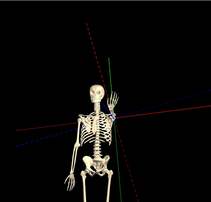
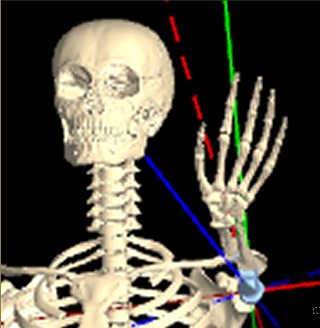
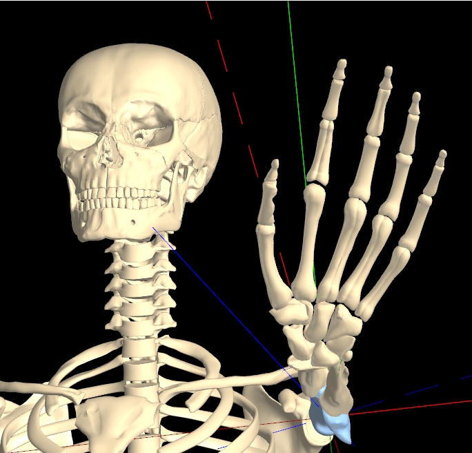
From these figures, it should be clear that the Distance control in KineBody doesn’t behave the same as a conventional Zoom control. Hence, the alternative terminology.
As you might have surmised, there are some assumptions required to make this work. The size of your monitor, as well as its distance from your eyes, are two key parameters required to express KineBody’s size in terms of distance. The distance calibration in KineBody currently assumes a screen 0.2m high, positioned about 0.7m from the eyes. If your monitor size or eye-to-screen distance differs, the distance calibration in KineBody may be inaccurate. However, what actually matters is the ratio of these parameters: 2/7, or ~ 0.29. If your monitor size is 0.3m, but your eye-to-screen distance is about 1.0m , the calibration will be close. Ultimately, however, the calibration depends on KineBody’s physical size. That is, if your monitor is large and close to your eyes, KineBody will appear larger or closer than its nominal 1.8m height would suggest. So, accurate calibration isn't essential. (On the other hand, if you desire precise calibration, a custom distance calibration widget is planned for a future edition of KineBody).
[Note; the distance calibration may be incorrect, if you're using Windows and Firefox. Windows allows you to increase the size of text & other items, e.g., to 125% of its normal value. This Windows setting is used within Firefox to change the size of graphics elements, with the result that the distance calibration may be incorrect. You can correct the calibration by using the Firefox's zoom control (main menu>View>Zoom). For example, if your Windows text size is 125%, set the Firefox zoom to 80%: Under the Zoom menu, press Reset & then Zoom Out, then Zoom Out again. (to change from 100% to 90% to 80%). Of course, this all presumes that your screen size & distance follow the 0.29 ratio above. Any other value will cause additional discrepancies].
A related parameter is the location of the ‘zero’ distance point, which may become relevant when you’re examining KineBody at close distance. KineBody currently defines zero distance at point in the middle of the ribcage, as shown by the intersection of the red, blue, and green axes when full skeleton movement is enabled. [This point is more or less arbitrary: it actually represents the geometrical centroid of all the spatial points used to define the the ribcage; note that this is not the same as the center of gravity, of either the ribcage or the full skeleton].
Bone & Joint Hierarchy
KineBody is currently composed of 160 bones (or identifiable parts). KineBody Basic (our free edition) includes 39 joints. Some of the bones are connected rigidly to each other, forming 'units': the skull, thorax, hands, feet, and mandible [5]. KineBody Pro (our subscription edition) provides articulated hands, instead of rigid ones, offering 18 additional joints each, and articulated feet, offering 17 joints each. Following is an organized list of the bones and joints, showing their relation to each other. Contents of the bone units are listed thereafter.
Every joint has an associated distal bone, so these are listed as together, e.g. ‘sternoclavicular joint / clavicle’. Indentation of text indicates a serial connection, e.g., the acromio-clavicular joint (indented relative to the previous line) connects the clavicle to the scapula. Joints sharing the same indentation share the same parent bone or unit. 'L/R' indicates that the bone or joint appears as either Left or Right; this designation is inherited by all bones or joints lower in the hierarchy.
- thorax (unit)
- sterno-clavicular joint / clavicle (L/R)
- acromio-clavicular joint / scapula
- gleno-humeral joint / humerus
- humero-ulnar joint / ulna
- radio-ulnar joint / radius
- radio-carpal (wrist) joint / hand (unit) <Basic edition>
- radio-carpal (wrist) joint / proximal carpus (unit) <Pro edition>
- mid-carpal joint / central pillar (unit)
- carpo-metacarpal 1 joint / metacarpal 1
- metacarpo-phalangeal 1 joint / proximal phalanx 1
- interphalangeal (IP) 1 joint / distal phalanx 1
- metacarpo-phalangeal 1 joint / proximal phalanx 1
- metacarpo-phalangeal 2 joint / proximal phalanx 2
- proximal interphalangeal (PIP) 2 joint / intermediate phalanx 2
- distal interphalangeal (DIP) 2 joint / distal phalanx 2
- proximal interphalangeal (PIP) 2 joint / intermediate phalanx 2
- metacarpo-phalangeal 3 joint / proximal phalanx 3
- proximal interphalangeal (PIP) 3 joint / intermediate phalanx 3
- distal interphalangeal (DIP) 3 joint / distal phalanx 3
- proximal interphalangeal (PIP) 3 joint / intermediate phalanx 3
- carpo-metacarpal 4 joint / metacarpal 4
- metacarpo-phalangeal 4 joint / proximal phalanx 4
- proximal interphalangeal (PIP) 4 joint / intermediate
phalanx 4
- distal interphalangeal (DIP) 4 joint / distal phalanx 4
- proximal interphalangeal (PIP) 4 joint / intermediate
phalanx 4
- metacarpo-phalangeal 4 joint / proximal phalanx 4
- carpo-metacarpal 5 joint / metacarpal 5
- metacarpo-phalangeal 5 joint / proximal phalanx 5
- proximal interphalangeal (PIP) 5 joint / intermediate phalanx 5
- distal interphalangeal (DIP) 5 joint / distal phalanx 5
- proximal interphalangeal (PIP) 5 joint / intermediate phalanx 5
- metacarpo-phalangeal 5 joint / proximal phalanx 5
- carpo-metacarpal 1 joint / metacarpal 1
- C7T1 joint / C7 vertebra
- C6C7 joint / C6 vertebra
- C5C6 joint / C5 vertebra
- C4C5 joint / C4 vertebra
- C3C4 joint / C3 vertebra
- C2C3 joint / C2 vertebra
- C1C2 joint / C1 vertebra
- Occiput-C1 joint [1] / skull (unit)
- tempero-mandibular joint (TMJ) / mandible (unit) [2]
- T12L1 joint / L1 vertebra
- L1L2 joint / L2 vertebra
- L2L3 joint / L3 vertebra
- L3L4 joint / L4 vertebra
- L4L5 joint / L5 vertebra
- L5S1 joint [3] / sacrum + coccyx [4]
- sacro-iliac joint / hip (innominate) (L/R)
- ilio-femoral (hip) joint / femur
- patello-femoral joint / patella
- tibio-femoral joint / tibia
- tibio-fibular joint / fibula
- talo-crural (ankle) joint / foot (unit) <Basic edition>
- talo-crural (ankle) joint / talus <Pro edition>
- sub-talar joint / calcaneus
- midtarsal / midfoot (unit)
- TMT 1 joint / metatarsal 1 (unit)
- MTP 1 joint /
proximal phalanx 1
- IP 1 joint / distal phalanx 1
- MTP 1 joint /
proximal phalanx 1
- MTP 2 joint / proximal phalanx 2
- PIP 2 joint / intermediate phalanx 2
- DIP 2 joint / distal phalanx 2
- PIP 2 joint / intermediate phalanx 2
- MTP 3 joint / proximal phalanx 3
- PIP 3 joint / intermediate phalanx 3
- DIP 3 joint / distal phalanx 3
- PIP 3 joint / intermediate phalanx 3
- MTP 4 joint / proximal phalanx 4
- PIP 4 joint / intermediate phalanx 4
- DIP 4 joint / distal phalanx 4
- PIP 4 joint / intermediate phalanx 4
- MTP 5 joint / proximal phalanx 5
- PIP 5 joint / intermediate phalanx 5
- DIP 5 joint / distal phalanx 5
- PIP 5 joint / intermediate phalanx 5
Abbreviations
TMT: tarso-metatarsal
MTP: metatarso-phalangeal
IP: interphalangeal
PIP: proximal IP
DIP: distal IP
- TMT 1 joint / metatarsal 1 (unit)
- midtarsal / midfoot (unit)
Footnotes
[1] The Occiput-C1 joint cannot be independently moved - it can only be moved as part of the neck (joint) group.
[2] 'Mandible' is used as the name of a bone unit, and as a bone within that unit, i.e., the mandible unit includes the
mandible bone + lower teeth as well.
[3] The L5S1 joint cannot be independently moved - it can only be moved as part of the lumbar spine (joint) group.
[4] The coccyx was omitted in the original ('KineMan') version.
[5] The terminology was changed from 'bone group' to 'bone unit', as of March 2021, to avoid confusion with other types of groups (i.e., groups of bones used for copy/paste and show/hide selection, and joint groups).
[Note that this hierarchy defines the organization of linkages specifically for use by KineBody; it doesn’t necessarily reflect the groupings normally used for kinesiological or biomechanics study. For example, for KineBody operation, the humero-radial joint is absent, and the proximal & distal radioulnar joints are combined into a single entity].
Bone unit contents:
| Unit | Contents |
| Skull |
(L/R, 2 each): parietal, temporal, ethmoid (orbital & cribriform plates***), maxilla, palatine, zygomatic, lacrimal,
teeth (upper); 3 nasal conchae
(non-L/R: 1 each): occiput, frontal****, sphenoid, nasal, crista galli, vomer, ethmoid (perpendicular plate etal***) |
| Thorax | 24 ribs, 12 T vertebrae, 1 sternum |
| Hand <Basic edition> |
1 each: hamate, lunate, capitate, scaphoid, trapezium, trapezoid, triquetrum, pisiform; 5 metacarpal, 14 phalanges |
| Proximal carpus <Pro edition> |
1 each: lunate, scaphoid, triquetrum, pisiform |
| Central pillar (of hand) <Pro edition> |
1 each: hamate, capitate, trapezium, trapezoid; metacarpals 2 & 3 |
| Foot | 1 each: talus, calcaneus, cuboid, navicular; 3 cuneiform, 5 metatarsal, 14 phalanges, 2 sesamoid |
| Metatarsal 1 <Pro edition> |
1 metatarsal, 2 sesamoid; |
| Midfoot <Pro edition> |
1 each: navicular, cuboid; 3 cuneiform; 4 metatarsal |
| Mandible | 1 mandible (bone), 2 teeth lower (L/R) |
*** The ethmoid bone in this set is split into distinct parts, including the orbital and cribriform plates, plus 'perp' ( perpendicular plate) and 'repg' (lamina perpendicularis
pars repugnante).
**** A portion of the frontal bone is this set shows as 'sinf' (for 'sinus frontalis').
Body Options
KineBody Pro provides users with a choice of 3 bodies: two ‘median’ adult skeletons: male & female, plus a second adult male dubbed ‘original’ or ‘KineMan’, which was the sole skeleton offered in prior versions of this software (2013-2020).
Bones for all three of these skeletons were obtained (or derived) from a commercially available bone dataset [1]. This bone dataset includes male & female bones; the female bones are typically just scaled replicas of the male bones, i.e., the shapes are identical. The pelvic bones are an exception: they’re shaped differently for male vs female, to represent the natural differences in those bones.
The KineMan original skeleton was assembled from the male bone data “as is”, for the most part, i.e., generally without modification in size or shape. Bone positions were fine-tuned for improved joint accuracy and initial posture.
The original skeleton was adequate for it’s primary original design goal, which was to accurately depict 3D human joint behavior, for all high-mobility joints. A secondary design goal was to serve as a simple human pose demonstration tool, for use in applications such as athletics/martial arts/ dance, visual & performing arts, and similar. For many of these purposes, the overall height of KineBody skeletons is irrelevant: you can visually “scale” the body size simply by adjusting the body distance. Similarly, the sizes and proportions of bones is often irrelevant. For instance, the bone sizes are unimportant if your goal is to demonstrate/observe joint mechanics.
One motivation for developing new body types arose while investigating the validity of the scale and proportions of the original dataset. Upon comparing the dimensions of the original/KineMan male skeleton and an ‘average’ male, several discrepancies became apparent. The height of this skeleton is 1.85m (6’1”), whereas the average for U.S. adult male height is closer to 1.75m (5’9”), and not significantly taller for other parts of the world [2]. Furthermore, the proportions of the head and neck appear to be relatively small & large (respectively): the ‘original’ head height is approximately 0.105 of body height, whereas many sources suggest that typical human heads are larger, in the range of 0.12-0.133 of height [3]. The tibias of the original data set also appear to be unusually long.
The two median skeletons were derived from the original KineMan skeleton, by rescaling the individual bones so as to closely align with median (i.e. 50th percentile) body surface measurements, obtained from a population of over 6000 American male and female individuals [4]. The body surface measurements weren’t always sufficient for this task, so the measurements were supplemented with skeletal proportions from CT scans of an individual adult male [5], and corroborated with images of average body shapes [6]. The female median skeleton was constructed likewise, but using the special female pelvis bones provided with the original data set.
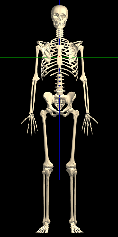
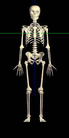
Many of the differences in proportions between the original and median male skeletons are evident from a cursory view: the median body has a larger head, shorter neck, and shorter tibias, as shown in the Figure below. Some other differences are subtle: the median body has a narrower ribcage, wider shoulders and a flatter clavicle inclination, larger hands and longer humerii.
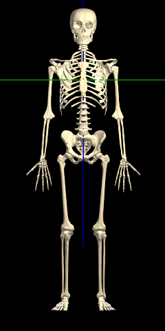
Between the male & female median skeletons, the only immediately obvious difference is in the hips. All the other differences are very subtle: when you change between the median male & female bodies, it appears that the female is simply a smaller (or farther) version of the male:
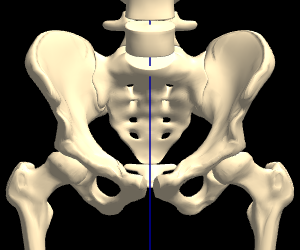
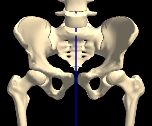
However, when the female is scaled to the same height as the male (via a distance change), and overlaid, the differences in proportions become more evident (hover the image, to alternate between Male & Female):
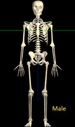
[ Hover to alternate image ]
[1] Anatomium.com (P1 dataset)
[2] ourworldindata.org/human-height
[3] Human Proportions for Figure Drawing,
or Proko.com, Human Figure Proportions
[4] The 2012 Anthropometric Survey of US Army Personnel
[5] Visible Human Project
[6] By Nikolay Lamm, as reported in The Atlantic, This is the Average Man's Body